
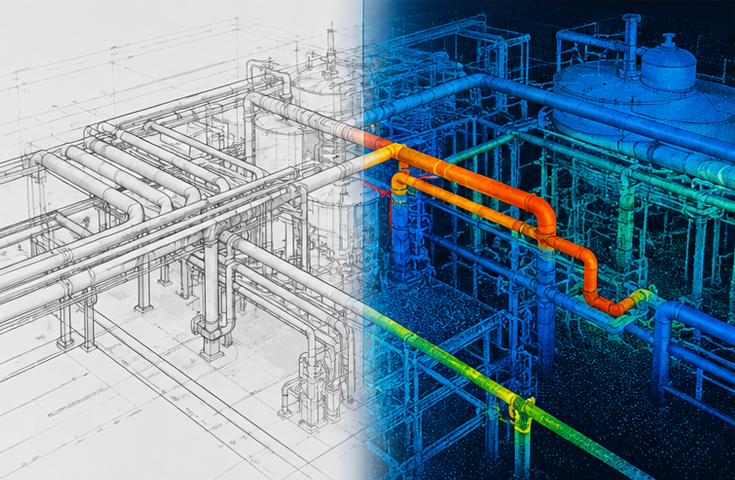
A fifteen-year-old isometric still shows a pipe run where it used to sit, not where it sits today. Nobody records that kind of drift as a change; it just shows up as an unplanned clash during a shutdown. Laser scanning and point cloud modeling catch that drift before design work starts, verifying the existing plant exactly as it stands rather than as an old drawing says it should.
Nobody has ever lost a project by scanning too much of an existing plant. Projects get lost trusting paper that was accurate once, a decade and a dozen unrecorded tie-ins ago. That gap between drawing and reality is the entire risk profile of a brownfield revamp, and it's closeable before a single line is drawn on the new design.
Over 70% of brownfield plant modification delays trace back to "as-designed" paper drawings that no longer reflect what's actually installed. Integrating 3D laser scanning (scan-to-BIM) at Pre-FEED replaces guesswork with millimetric field accuracy, eliminating pipe-rack spatial clashes, hot-work site modifications, and unplanned downtime during tie-ins.
At Acufore, we build laser scanning into Pre-FEED as standard practice, not an optional add-on, so the model everyone designs against matches the plant that's actually there.
Drawing from over 90,000 engineering hours across 1,400+ industrial projects, including plant BIM, tie-in engineering, and shutdown planning for live facilities, here's how we close the gap between a legacy drawing and a fabrication-ready model.
On this page ▾
01The Brownfield Reality: Legacy Drawings vs. What's Actually There
Every brownfield plant drifts from its documentation the same way: a maintenance team reroutes a line during an outage, a platform gets modified for access, a tie-in goes in under time pressure and the redline sits in a binder instead of the CAD system. None of this is negligence. It's just how decades of live operation actually work.
The Plain Business Consequence
Three risk patterns show up on almost every revamp, and each one turns into cost the moment it's discovered on site instead of on a screen.
- As-built vs. as-is discrepancies: decades of minor field modifications, unrecorded pipe rerouting, and structural additions that never made it back to the drawing office.
- Thermal & structural settlement: operating steel flexes, foundations settle, and hot piping shifts away from its theoretical installation coordinates.
- Tight spatial constraints: squeezing new equipment into a live brownfield environment leaves zero tolerance for error during a shutdown installation window.
Frameworks like ISO 19650 exist precisely because most facilities never had that discipline applied to them in the first place.
| Approach | Workflow | Result |
|---|---|---|
| Conventional | Paper drawings → manual tape measurement → design CAD → site clash on installation | $$$ change order |
| Scan-to-BIM | 3D laser scan → millimetric point cloud → data-rich BIM → automated clash audit | Zero site rework |

02What a Point Cloud Actually Buys You
A laser scan converts the real, current-state facility into a dense, dimensionally accurate point cloud: a 3D record of exactly where everything actually is, not where a drawing says it should be. But "accurate" isn't a marketing word here; it's a defined standard. The USIBD Level of Accuracy specification gives the industry a common way to state, in advance, exactly how tight that dimensional tolerance needs to be for the decision it's supporting, tighter for fabrication and tie-ins, looser for general spatial planning.
That distinction matters more than most people scoping a scan realize. A dense, visually convincing point cloud with no real survey control behind it is just floating geometry that happens to look precise. The number that matters isn't how many points were captured. It's whether those points were tied to a control network you'd trust a fabrication drawing to.
In practice, terrestrial laser scanners emit millions of pulses per second across the facility, and the reflections build a high-density point cloud accurate to roughly ±1mm under good conditions, capturing every beam, pipe flange, vessel nozzle, structural column, and cable tray as it actually sits today.
Terrestrial Laser Scan
Point Cloud Registration
Intelligent CAD/BIM Hybrid
Automated Clash Audit
Importing that point cloud directly into a multi-disciplinary BIM platform, whether AVEVA E3D, Autodesk Plant 3D, or Tekla, changes what's possible at Pre-FEED: design teams walk the facility virtually and take exact dimensional checks without sending people into hazardous plant zones; tie-in locations, flange orientations, and nozzle elevations get verified against physical reality before detailed engineering starts; and rigging pathways, crane lift radii, and equipment removal envelopes get simulated to confirm modules actually fit through existing structures.
The Plain Business Consequence
Skip this step and you're back to manual tape measurement and drawing-office guesswork. Tie-in locations and nozzle elevations end up verified on site instead of on screen, which is exactly where hazardous-zone man-hours and schedule risk creep back in. Skipping the scan to save two weeks rarely saves anything: the two weeks tend to come back later as field rework, at a much worse exchange rate.
03Eliminating Spatial Clashes: Hard vs. Soft Collisions
Once the existing plant exists as an accurate model, new piping, pipe racks, or skid packages get modelled directly into it, not into a drawing, into the real geometry. Automated clash detection then audits the whole spatial model, and the results generally split into three types.
| Clash Type | What It Means | Risk If Undetected |
|---|---|---|
| Hard clash | A new pipe or structure physically intersects an existing plant member, e.g. a new pipe rack beam hitting an existing vessel nozzle. | Total site stoppage, field cutting, re-welding, heavy change orders |
| Soft / clearance clash | Insufficient space for thermal expansion, insulation thickness, or maintenance access, e.g. a valve wheel too close to a walkway. | Failed safety audits, restricted operator access, premature pipe failure |
| Constructability clash | A pre-assembled skid or spool can't physically be manoeuvred into position through existing overhead steel. | Extended shutdowns, crane standby costs |
Every clash caught here shows up on screen while it's still a design change instead of a field problem. Academic work on reconstructing simulation-ready models from point cloud data makes the same point from the modelling side: brownfield planning consistently suffers from partial, inconsistent as-built data, and closing that gap is what actually makes downstream design decisions reliable. Early spatial validation also feeds straight into funding accuracy, see our companion guide on AACE Class 5/4 CAPEX estimation for how spatial de-risking protects the budget against scope creep.
The Plain Business Consequence
A discovered clash in the field doesn't just cost the rework. It costs a shutdown day, a re-issued fabrication drawing, and a difficult conversation about why nobody caught it sooner. We'd rather have that conversation during a model review, on a screen, three months before mobilization, where the fix is a design change, not a crane sitting idle.
Scan to fabricationFrom Scan to Fabrication: How Acufore Closes the Gap
A 3D scan is only as valuable as the engineering built on top of it. For us at Acufore, spatial verification is a design requirement, not a separate service bolted onto a revamp. It sits directly inside Pre-FEED & feasibility engineering, verifying existing plant conditions before new equipment gets laid out, while changes are still a redline instead of a re-fabrication.
Point Cloud Scan
CAESAR II Stress Analysis
Tekla Fabrication BIM
CAD-to-CNC Export
Site Installation
Acufore acts as a single point of accountability across the full scan-to-fabrication chain:
Laser Scan & Survey Control
Every scan is tied to a real survey control network, not floating geometry that only looks precise, so the model can be trusted for fabrication-grade decisions.
LOA-Matched Registration
We register the point cloud to the Level of Accuracy the decision actually needs: tighter for fabrication and tie-ins, appropriately scoped for general spatial planning.
Equipment & Skid Modelling
New equipment and skid envelopes are modelled directly into the scanned geometry, so rigging pathways and crane lift radii are confirmed before mobilization.
Automated Clash Detection
Hard, soft, and constructability clashes are audited against pipe racks, steel, and platforms while a fix is still a redline, not a field problem.
Fabrication-Ready Handoff
CAESAR II stress analysis and Tekla fabrication BIM carry the model through to CAD-to-CNC export, aligned to BS EN 1090 and 3.1 mill certification for offshore-fabricated spools.
Integrating 3D laser scanning into early brownfield engineering delivers outcomes that show up directly in the schedule and the budget: up to 90% reduction in field rework by eliminating on-site torch cutting and emergency spool remanufacturing, shortened shutdown windows as pre-fabricated skids bolt straight into existing tie-in points, and lower HSE liability from fewer contractor man-hours spent measuring steel inside hazardous process zones.
For projects sourcing fabricated steel through the UK-India corridor, this same paper trail feeds directly into the procurement and duty questions covered in our UK-India CETA guide.