
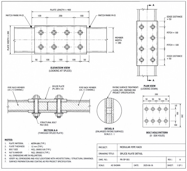
A pipe rack welded into one continuous frame at the fabrication shop is a single object: it ships as one piece, or it gets cut apart and re-welded at site, which defeats the point of building it as a module in the first place. Design for Manufacturing treats the break points between shippable sections as a design decision made at the model stage, not a problem solved with a cutting torch once the steel already exists. Under BS EN 1090 Execution Class 2, every one of those bolted splices still has to carry its full design load as a genuinely engineered joint, not a site-welded connection wearing bolts for show.
A shot-blasted, coated faying surface needs roughly half the bolts of an untreated one to carry the identical load, a decision made with a surface-treatment note on a drawing, not a bolt catalogue. Bolted connections eliminate the site-welding costs a shop never has to think about: a qualified welder physically present, weather protection over the joint, an NDT crew, and an inspector to sign it off, all inside a live construction schedule. But that only holds if connection category, faying surface, and splice hole alignment are decided at the model stage.
At Acufore, every modular pipe rack is detailed for bolt-together assembly from the first model, so nothing gets re-interpreted at the shop-to-site handoff.
Drawing from over 90,000 engineering hours across 1,400+ industrial projects, here's how a bolt-together pipe rack actually gets detailed, a worked example of what a faying surface decision does to bolt count, and what recent testing says about slip factor and preload control.
On this page ▾
01Why Bolt-Together, Not Weld-Together
Site welding carries costs a shop never has to think about: a qualified welder physically present, weather protection over the joint, an NDT crew to inspect it, and an inspector to sign it off before work continues, all inside a live construction schedule rather than a controlled shop floor. Every one of those requirements disappears the moment a connection is designed to be bolted instead. A bolted joint can be fully qualified, drilled, and trial-fitted in the shop, then simply bolted together again at site by a smaller crew with no welding qualification at all.
That's the entire logic behind treating modular pipe rack & process skid engineering as bolt-together by default: every joint that can reasonably be bolted instead of welded is one less site welding inspection standing between the module and mechanical completion.
The Plain Business Consequence
Every joint site-welded instead of bolted needs a qualified welder present, weather protection over the joint, and an NDT crew and inspector to sign it off, all inside a live construction schedule. That's schedule risk and cost that a shop-only connection removes entirely.
02Bolted Connection Categories Under Eurocode 3
BS EN 1090-2 governs how a steel structure gets fabricated and erected, but the connections themselves are designed to Eurocode 3, specifically EN 1993-1-8, which splits bolted connections into five categories depending on whether the bolts are preloaded and whether the joint is allowed to slip.
| Category | Preload | Behaviour |
|---|---|---|
| A: Bearing type | Not required | Shear resisted by bolt bearing once the joint takes up its clearance |
| B: Slip-resistant (SLS) | Required | No slip at service loads; may slip into bearing at ultimate |
| C: Slip-resistant (ULS) | Required | Must not slip at all, even at ultimate load |
| D: Non-preloaded (tension) | Not required | Suitable for static tension, not for frequently varying loads |
| E: Preloaded (tension) | Required | Preloaded 8.8 or 10.9 bolts for tension joints |
Most pipe rack splices sit in Category A or B: bearing-type where the joint can tolerate a small amount of slip, slip-resistant where it can't, typically because the rack is carrying dynamic piping loads or the connection sits somewhere a small shift in geometry would misalign the piping either side of it. Slip resistance itself depends on the faying surface, not just the bolt: a shot-blasted and coated surface and an as-rolled, unprepared one can differ enough in slip factor to change how many bolts a joint actually needs, which is exactly the kind of detail a preloaded bolt connection has to specify explicitly rather than assume.
"Frictional resistance is highly dependent on the surface conditions."
— Steel Construction Info (BCSA and SCI), Preloaded bolting
The Plain Business Consequence
Get the connection category or faying surface treatment wrong and the joint either can't carry its design load, or needs more bolts than the layout has room for, discovered only once the splice is already detailed and the steel is on order.
03Worked Example: What the Faying Surface Does to Bolt Count
The slip factor is the easiest number in a slip-resistant joint to get wrong, because it comes from a surface treatment rather than a bolt catalogue. To see how much it matters, take one splice and change only the surface. The joint uses M20 grade 8.8 preloaded bolts in standard clearance holes, a double cover plate so each bolt clamps two friction surfaces, Category C so it must not slip even at ultimate load, and a design shear of 1,000 kN across the joint.
Fp,C = 0.7 × fub × As = 0.7 × 800 × 245 = 137.2 kN
Fs,Rd = ks × n × μ ÷ γM3 × Fp,C (ks = 1.0, n = 2, γM3 = 1.25)
| Class | Surface Treatment | Slip Factor μ | Resistance per Bolt | Bolts Needed |
|---|---|---|---|---|
| A | Blast-cleaned, loose rust removed, not pitted | 0.50 | 109.8 kN | 10 |
| B | Blast-cleaned, coated with alkali-zinc silicate paint (nominal 60 µm) | 0.40 | 87.8 kN | 12 |
| C | Wire-brushed or flame-cleaned, loose rust removed | 0.30 | 65.9 kN | 16 |
| D | As rolled, untreated | 0.20 | 43.9 kN | 23 |
Per bolt, a class A surface resists 2.5 times what an as-rolled surface does. Across the joint that is 10 bolts against 23: more than twice the holes to drill, the bolts to buy and the tightening to inspect, decided by a surface treatment note on a drawing. It is also why standardizing one faying surface treatment across the rack matters more than it looks like it should.
This is a sizing illustration, not a design check. It uses the CEN-recommended γM3 values (1.25 at ultimate, 1.1 at serviceability) from EN 1993-1-8:2005, the edition SCI and BCSA guidance still references. Confirm the edition and National Annex your contract calls up, since the second-generation EN 1993-1-8:2024 is now published.
- Preloaded bolt, property class 8.8 or 10.9, in a standard clearance hole
- Faying surfaces (highlighted): two friction interfaces, treated to the specified slip class
- Cover plate, one each side of the joint
- Joint centreline: the members butt with a small gap and the load crosses by friction through the cover plates
- Match-mark stamped on both halves in the shop, so site knows what mates with what
- Identical bolt pattern on every splice of this type
Every splice gets match-marked in the shop just like the diagram above: a stamped or painted reference that tells the site crew which piece bolts to which, in which orientation, without anyone re-deriving it from a drawing set at 6am in the rain. It's also worth separating transport bolts, the temporary fasteners that hold a module together rigid enough to survive shipping, from the permanent structural bolts that carry the actual design load once erected; treating the two as interchangeable is a common source of site rework.
Across 1,400+ completed industrial projects, the pattern holds every time: a bolted joint that still needs match-drilling on site isn't a modular connection. It's a welded joint that happens to use bolts.
The Plain Business Consequence
Leave hole alignment to be resolved on site, or leave the faying surface unspecified, and a bolt-up crew becomes a fitting crew: drilling and reaming connections that were supposed to be a same-day bolt-together task, or discovering the joint needs more than twice the bolts the layout has room for.
04What Testing Says About Slip Factor and Preload
Three findings from published testing and guidance change how a splice should be specified, not only how it is calculated.
Prepared surfaces can wait for site
Faying surfaces prepared in the shop often sit for weeks before the module is bolted up. Research by R. J. Lark, summarised in the SCI and BCSA preloaded bolting guidance, found no appreciable loss of slip factor after 40 days of exposure, for carbon steel and weathering steel alike. The same guidance says oil and grease must be cleaned off before assembly, while light rusting does no harm. So prepare and inspect the surfaces in the shop, and write the site clean-down into the bolt-up procedure.
A tested slip factor sits below the best result
For a surface treatment that is not on the standard list, BS EN 1090-2 Annex G requires a slip factor test. A test report published by coating manufacturer Hempel shows why the design value should come from the report rather than the best result: five tests gave a mean slip factor of 0.512 and a characteristic value of 0.46, but because an extended creep test was required, the nominal value assigned was 0.40. Ask for the Annex G report and design to the nominal value it supports.
Torque alone is a weak way to control preload
BS EN 1090-2 gives four tightening methods for preloaded bolts: torque, combined, HRC and direct tension indicator. The SCI and BCSA guidance, written for bridge steelwork but resting on the same execution standard, warns that the torque-to-preload relationship can vary by as much as ±30% from bolt to bolt even within one batch, and by more if the bolts are coated. It also notes that only K0 class assemblies are currently manufactured in the UK, while the torque method calls for K2. Choose a tightening method that suits the assemblies actually available, such as direct tension indicators, and confirm supply before the drawings are issued.
The Plain Business Consequence
Specify a torque method the available bolt assemblies don't actually support, and either the tightening inspection fails on site or the preload is wrong by up to 30% bolt to bolt, undermining the slip resistance the whole joint was designed around.
DFM deliveryFrom Model to Bolt-Up: What Acufore Delivers
None of these decisions are expensive to make at the model stage. Made late, after the steel is already cut, every one of them gets expensive fast, a pattern McKinsey's review of modular construction found holds well beyond pipe racks: "changes later in the process are both more costly and more difficult." Acufore builds bolt-together detailing into the model from day one:
Standardized Bolt Sizing
One set of bolt sizes and grades across the rack, cutting the number of unique parts the shop has to track and stock.
Shop Match-Drilling
Every splice plate match-drilled and trial-fitted in the shop, never left for hole alignment to be resolved on site.
Stress-Informed Break Points
Module break points placed at the low-stress locations the same CAESAR II stress model already identifies, not wherever the layout happens to leave a gap or a transport-driven guess made afterward.
Tested Faying Surface Spec
One faying surface treatment specified consistently across all slip-resistant joints, backed by a BS EN 1090-2 Annex G test report for anything not on the standard slip factor list.
Confirmed Tightening Method
A tightening method chosen to suit the bolt assemblies actually in stock, with supply confirmed before drawings are issued, rather than specified in the abstract.
A rack detailed for bolt-together assembly from the start delivers outcomes that show up directly at site: faster site erection, as a bolt-up crew moves through a module in a fraction of the time a welding crew needs; lower site skill requirement, with no welding qualification, weather enclosure, or site NDT crew needed for the splice itself; and first-pass EXC2 compliance, with connection category, bolt grade, and faying surface specified once, in the shop, not re-decided at site.
| Figure | What It Measures | Source |
|---|---|---|
| 20–50% | Faster delivery of modular projects compared with site-built ones | McKinsey, 2019 (mostly buildings) |
| Up to 25% | Expected cut in project labour cost from moving work offsite | McKinsey, 2019 |
| 3–12% | Productivity gain from design shaped around the manufacturing process | McKinsey, 2019 |
| Up to +10% | Possible increase in total project cost where road-transport rules restrict module size | McKinsey, 2019 |
| ±30% | Bolt-to-bolt variation in the torque-to-preload relationship, even within one batch | SCI and BCSA guidance |
| 2.5× | Slip resistance per bolt, class A surface against class D, in the worked example above | Calculated, EN 1993-1-8 |
Most of the modular-construction data above comes from buildings rather than industrial steel, and cost savings are still more the exception than the rule (outcomes ranged from a 20% saving to a 10% increase), so read it as direction rather than a forecast for your rack. The transport line is why module break points, once the stress model has proposed them, still get checked against the road envelope before the drawings are issued. This is the same discipline that sits behind a turnkey engineering scope: the connection design, the fabrication drawings, and the site bolt-up sequence all trace back to one model, so nothing gets re-interpreted at the handoff between shop and site.