1. Introduction
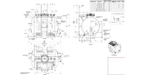
This custom horizontal pressure vessel was designed for a North American client. It is a 54″ I.D. stainless steel process vessel with a nominal capacity of 710 US gallons (738 gallons brim-full), built to ASME Sec. VIII Div. 1 for +40 PSIG and full vacuum at 450°F. The project involved specialized pressure vessel design and engineering.
The project scope covered engineering evaluation and drafting of the General Arrangement (GA) drawing, starting from the client's initial design data sheet. The goal was to fit an internal thermal coil, nine connections including the manway, saddle supports, lifting attachments and a top access platform into one compliant 304/304L pressure boundary. This included detailed engineering and GA drawing development.
Summary
Five design problems were resolved with four targeted moves: dual head penetrations for the coil, stainless wear pads under the saddles, gusseted asymmetric saddles, and an integrated platform with lifting attachments. The result is an ASME-compliant GA drawing approved for construction.
Vessel Technical Specifications
| Item | Detail |
|---|---|
| Material | 304/304L stainless steel shell and heads, 308L weld filler |
| Design code | ASME Sec. VIII Div. 1 |
| Rating | +40 PSIG and full vacuum at 450°F |
| Shell and heads | 54″ I.D. × 1/4″ plate, ASME F&D heads with 1″ straight flange |
| Capacity | 710 gal nominal, 738 gal brim-full |
| Overall size | 95-3/8″ L × 95-7/16″ H (to ladder handrail) |
| Internal coil | 1″ Sch. 80 316L, 150# at 450°F, 225# hydro |
| Supports | SA36 gusseted saddles with 1/4″ 304L back-up pads |
| Nozzles and manway | 9 |
2. Challenges
Five engineering problems had to be solved before the drawing could be approved:
1. Internal thermal coil integration: The ASME-rated 316L coil had to pass through the vessel heads without crowding the other connections or weakening the pressure boundary.
2. Galvanic corrosion: Welding carbon steel saddles directly to the austenitic stainless shell risks bimetallic corrosion at the contact points.
3. Pressure and full vacuum service: Simultaneous internal pressure and full vacuum at 450°F concentrate stress at the saddle horns and at the head and nozzle geometry. These conditions require careful mechanical equipment analysis.
4. Drain clearance: The saddles had to clear the bottom drain piping while still carrying the vessel load.
5. Crowded top and ends: Eight process connections, an 18″ manway, a platform, a ladder, lifting pins and boom rests all had to fit within a compact footprint.
3. Approach
Four targeted moves resolved all five problems at the design stage:
1. Dual head penetrations for the coil (Challenge 1): Coil inlet and outlet (nozzles G and H) were placed on the right head at 15″ center-to-center spacing, using 1″ 3000# full couplings.
2. Stainless wear pads under the saddles (Challenge 2): 1/4″ 304/304L reinforcing pads were welded to the shell before saddle attachment, so the carbon steel saddles are never welded directly to the stainless shell.
3. Asymmetric gusseted saddles and engineered heads (Challenges 3 and 4): Full-width 1/4″ SA36 gussets and back plates counter stress at the saddle horns under vacuum. The asymmetric layout clears the drain piping. ASME F&D heads with 1″ straight flanges and 308L filler complete the pressure boundary. The support configuration also involved civil and structural engineering considerations.
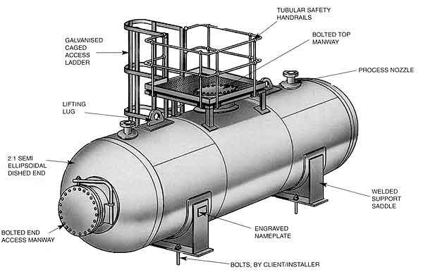
4. Integrated access and lifting package (Challenge 5): A 48″ × 24″ platform at 60″ elevation with a ladder and 42-7/8″ guardrail, plus lifting pins and boom rests gusseted to the heads. All nine connections, including the manway, were verified for fit-up and projection.
4. Conclusion
The project delivered an approved General Arrangement drawing for the 54″ I.D. stainless steel vessel, with all five design problems resolved before fabrication. Capacity exceeds the requirement by 9.2% (710 gal nominal) and 8.7% brim-full (738 gal).
The ASME Sec. VIII Div. 1 compliant design was approved for construction. Approval drawings, the spare parts list and calculations were submitted, and the drawing freeze was authorized, releasing cutsheets and long-lead procurement. This project demonstrates Acufore's capabilities in plant engineering services.
Explore Related Engineering Projects
Explore another Acufore project involving ASME vessels, storage tanks and associated structures: API Tanks, Vessels and Platform.